On this page
- How 24V and 48V ZPA conveyor MDR rollers separate transport from line pressure
- Slave roller transmission tiers: Polyurethane O-rings vs. Poly-V belts vs. steel chain
- Size photoeye zone length, roller pitch, and dynamic braking before selecting frame increments
- 1. The minimum three-roller support rule for roller pitch
- 2. Zone length sizing and dynamic braking stopping kinematics
- 3. Handling oversized SKUs: Dynamic Zone Allocation and Flexible Zone Recognition
- 4. Photoeye placement geometry and optical selection
- Singulation vs slug release conveyor logic: throughput math and jam protection
- 1. Singulation Mode (Single / Sequential Release)
- 2. Slug Mode and Cascaded Slug Release (Train / Block Release)
- 3. Worked throughput calculation at 120 FPM (36.58 m/min)
- 4. Mandatory 6-second Slug Jam Protection and on-the-fly mode switching
- 24V/48V DC power bus rules, sleep-timer duty cycles, and a worked 10-zone palletizer infeed
- 1. 24V and 48V DC power supply sizing and branch topology
- 2. Run-On-Demand sleep timer duty cycle and energy balance
- 3. Worked 10-zone (25.0 ft) robotic palletizer infeed sizing calculation
- 4. Factory acceptance testing (FAT) and commissioning verification table
- Technical basis and scope
Disabling dynamic braking on a 24V DC zone controller, selecting a 24-inch zone for a 420 mm shipping case at 120 FPM, or daisy-chaining 28 motorized rollers onto a single 20A power supply branch causes carton overruns, back-pressure package damage, end-of-line under-voltage failures, and unplanned line downtime. A zero pressure accumulation conveyor (ZPA) eliminates inter-package contact force (0 N line pressure) only when physical zone length exceeds maximum package length plus dynamic stopping distance and static clearance margin across every operating speed.
Specify a zero pressure accumulation conveyor by matching the 24V or 48V DC Motor Driven Roller (MDR) torque transmission (O-ring, Poly-V belt, or roll-to-roll chain) to unit mass, verifying the three-roller minimum pitch rule (P_roller ≤ L_min_case ÷ 3), sizing physical zone length (L_zone ≥ L_max_case + d_stop + c_margin) with dynamic braking enabled, and pairing singulation versus cascaded slug release modes with a properly sectioned DC power bus.
| Design parameter | Engineering formula or OEM specification | Operational boundary and failure prevented |
|---|---|---|
Roller center pitch (P_roller) |
P_roller ≤ L_min_case ÷ 3 (3.0 in. / 76.2 mm standard; 2.0 in. / 50.8 mm for short trays) |
Keeps at least 3 tread rollers beneath the shortest carton (≥ 229 mm on 3 in. pitch), preventing nose-diving and photoeye bounce |
Physical zone length (L_zone) |
L_zone ≥ L_max_case + d_stop + c_margin (18", 24", 30", 36" / 457–914 mm modular frames) |
Preserves a 100–200 mm zero-pressure air gap between halted cases at full conveyor speed |
Dynamic braking stopping travel (d_stop) |
d_stop = (v × t_scan) + [v² ÷ (2 × a_decel)] (~100 mm at 120 FPM with Hytrol Switch 2 = OFF) |
Prevents the 429 mm coast-to-stop overrun (Switch 2 = ON) that drives cartons across zone boundaries |
| Photoeye mounting offset | 100 to 150 mm (4 to 6 in.) upstream of the zone discharge roller |
Gives the MDR dynamic brake sufficient runway to halt the leading face inside its own zone |
Singulation vs. Slug throughput (120 FPM) |
CPM_sing = 31.5 CPM (1,162 mm pitch) vs. CPM_slug = 42.9–61.0 CPM (+36% to +94%) |
Delivers gapped single units to checkweighers/scanners or high-rate trains to layer/multi-pick palletizers |
| Slug mode jam protection | 6.0 s continuous photoeye blockage threshold (Hytrol Bulletin #669, p. 5) |
Reverts all upstream zones sequentially to zero-pressure hold if a carton stalls during slug flow |
| 24V DC power bus branch limit | ≤ 20 motors/cards per 20 A output branch (22.0–28.0 VDC window; trips at 19.0 V / 29.0 V) |
Eliminates end-of-line voltage sag and under-voltage fault lockouts during cascaded zone starts |
How 24V and 48V ZPA conveyor MDR rollers separate transport from line pressure
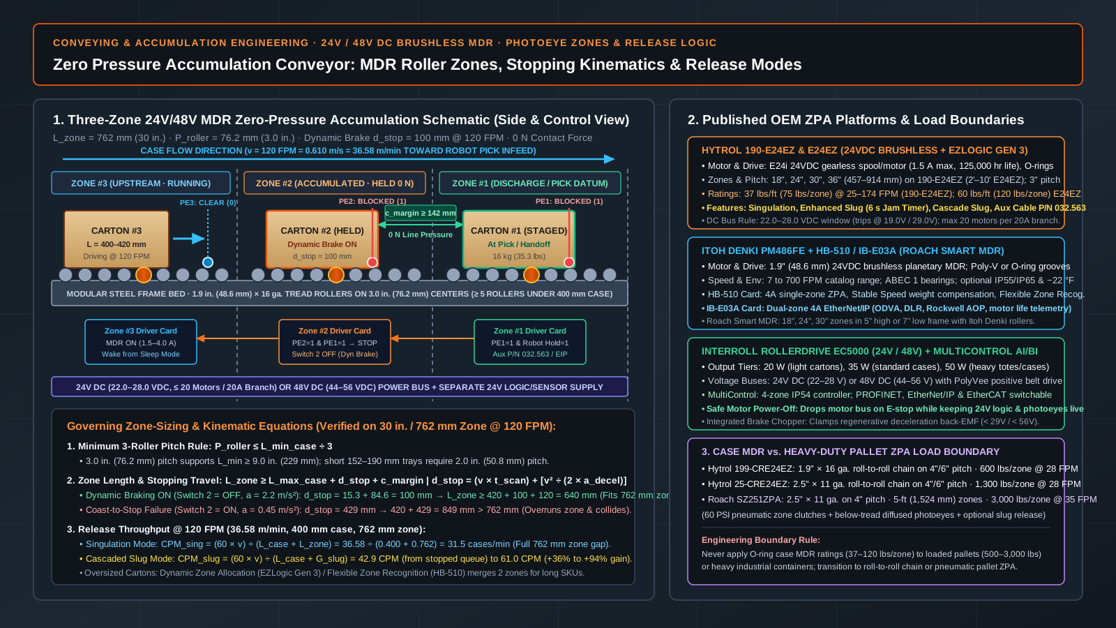
In a 24V or 48V DC brushless Motor Driven Roller (MDR) zero pressure accumulation conveyor, the conveying bed is divided into mechanically independent zones (18 in. to 36 in. / 457 to 914 mm long for shipping cases). Each zone contains one motorized roller (zpa conveyor mdr rollers, built around a 1.9 in. / 48.6 mm diameter steel tube housing a brushless DC stator, permanent-magnet rotor, planetary gearbox, and Hall-effect commutation sensors, or an external brushless spool motor) that drives 4 to 8 adjacent non-powered slave rollers via polyurethane O-rings, multi-ribbed Poly-V belts, or precision steel chains. Each zone pairs its motor with a local photoelectric presence sensor (photoeye) and a microprocessor driver card.
Because a zone’s MDR runs only when a package is entering or transiting that zone and halts immediately when its discharge photoeye is blocked while the next zone downstream is occupied, queued cartons wait with zero inter-package contact force (0 N). Within the broader conveying systems collection, this zone-by-zone decoupling separates positive package transport from accumulation buffering ahead of case sealers, checkweighers, and robotic palletizers.
| OEM ZPA platform | Drive architecture and voltage | Standard zone lengths and roller pitch | Published load capacity and speed range | Control architecture and release modes |
|---|---|---|---|---|
Hytrol 190-E24EZ and E24EZ (EZLogic Gen 3) |
24 VDC brushless, gearless E24 / E24i motor (1.5 A nominal, 125,000 hr design life) driving 1.9 in. × 16 ga. rollers via O-rings |
18", 24", 30", 36" (457–914 mm) on 190-E24EZ (2' to 10' on E24EZ); 3.0 in. (76.2 mm) centers |
37 lbs/ft (75 lbs/zone) on 190-E24EZ at 25–174 FPM; 60 lbs/ft (120 lbs/zone) on E24EZ at 25–125 FPM |
Standalone EZLogic optical zone controllers with IOP hub (no PLC required); Singulation, Enhanced Slug (6 s Jam Timer), Cascade Slug, Sleep Feature, Dynamic Zone Allocation |
Itoh Denki PM486FE + HB-510 / IB-E03A (Roach Smart MDR) |
24 VDC brushless internal planetary gearmotor (1.9 in. / 48.6 mm DOM zinc-plated tube, ABEC 1 bearings, 4 A card rating) with O-ring or Poly-V grooves |
18", 24", 30" (457, 610, 762 mm) on Roach Smart MDR (5" high or 7" low frame); 2.0 in. to 3.0 in. (50.8–76.2 mm) pitch |
Medium case loads (up to 75–150 lbs/zone by gear ratio and belt tier); 7 to 700 FPM (2.1–213 m/min) catalog speed range |
CB-016S7 (basic PLC on/off); HB-510 (single-zone ZPA with Stable Speed and Flexible Zone Recognition); IB-E03A (dual-zone EtherNet/IP with DLR, Rockwell AOP, and motor life telemetry) |
Interroll RollerDrive EC5000 + MultiControl AI/BI |
24 VDC (22–28 V) or 48 VDC (44–56 V) brushless internal MDR in 20 W, 35 W, and 50 W output classes (PolyVee or O-ring) |
Modular zones (500 to 1,000 mm / 20"–40"); 50 to 100 mm (2"–4") roller pitch |
20 W (light cartons), 35 W (standard cases), 50 W (heavy totes/cases up to 250 kg / 551 lbs); variable start/stop ramps |
MultiControl 4-zone IP54 controller (PROFINET, EtherNet/IP, EtherCAT switchable), integrated brake chopper, separate motor vs. logic power bus, Single vs. Train Release, automatic Teach-In |
Heavy-Duty Pallet ZPA (Hytrol 199/25-CRE24EZ and Roach SZ251ZPA) |
Hytrol CRE24EZ: 24 VDC motor + roll-to-roll chain (1.9" × 16 ga. or 2.5" × 11 ga.). Roach SZ251ZPA: 230/460 VAC drive + 60 PSI pneumatic zone clutch (2.5" × 11 ga.) |
4 in. or 6 in. (101.6–152.4 mm) centers; 5-foot (1,524 mm / 60 in.) pallet zones on Roach SZ251ZPA |
Hytrol 199-CRE24EZ: 600 lbs/zone (28 FPM); 25-CRE24EZ: 1,300 lbs/zone (28 FPM). Roach SZ251ZPA: 3,000 lbs/zone (35 FPM) |
Unit-load accumulation for loaded pallets, Gaylords, and drums (EZLogic on CRE24EZ; below-tread diffused photoeyes + optional full-queue slug release on SZ251ZPA) |
Slave roller transmission tiers: Polyurethane O-rings vs. Poly-V belts vs. steel chain
Selecting the wrong mechanical transmission between the zone’s motorized roller and its slave idlers degrades stopping repeatability long before the motor reaches its thermal limit:
- Polyurethane O-rings (
3/16 in. / 5 mmcross-section, standard on Hytrol 190-E24EZ and E24EZ): Quiet, economical, and fast to restring during maintenance. O-ring transmission fits dry corrugated shipping cases up to37 lbs/ft(75 lbs/zoneon190-E24EZ) or60 lbs/ft(120 lbs/zoneonE24EZ). When decelerating cases heavier than35 kg (77 lbs)or handling cartons with wax, condensation, or oil residue, elastomeric O-rings stretch and slip in their grooves, increasing stopping distanced_stop. - Multi-ribbed Poly-V belts (
2-rib or 3-rib PJ profile, used on Itoh Denki PM486FE and Interroll RollerDrive EC5000): Flexible polyamide/elastomer V-ribbed belts engage precision-machined end caps on adjacent rollers, transmitting2.5× to 3.5×higher positive torque without belt slip. SpecifyPoly-V(PolyVee) slave drive whenever case mass falls between15 and 50 kg (33 to 110 lbs), when conveying smooth-bottomed plastic returnable totes, or when a robot pick datum requires crisp0.15 to 0.30 sacceleration and deceleration ramps. - Roll-to-roll precision steel chain (
#40, #50, or #60, used onHytrol 199-CRE24EZat600 lbs/zoneand25-CRE24EZat1,300 lbs/zone) or pneumatic clutch zones (Roach SZ251ZPA at3,000 lbs/zone): Never apply case-level1.9 in.O-ring MDR conveyors to empty pallet stacks or loaded pallets. Use our palletizing conveyor handoff guide to separate case-infeed accumulation from full-pallet discharge, and pair heavy pallet zones with the500 kgstack ratings in the pallet dispenser machine guide.
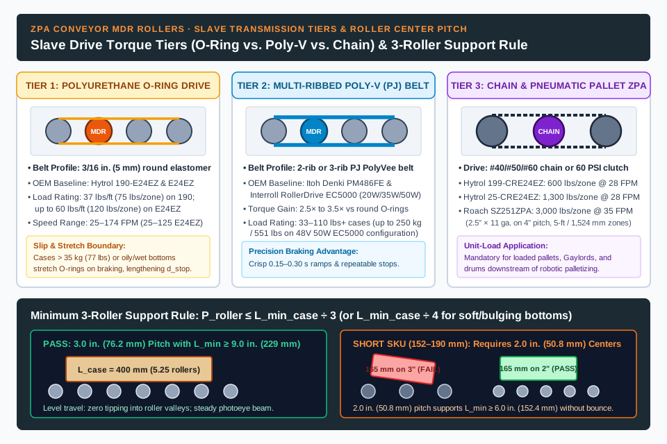
Key takeaway: Match the slave drive transmission to package mass and braking deceleration before comparing controller features—use 3/16 in. O-rings for dry corrugated cases up to 75–120 lbs/zone, 2/3-rib PJ Poly-V belts for 33–110+ lb cases or high-precision robot pick stops, and roll-to-roll chain (Hytrol CRE24EZ) or 60 PSI pneumatic clutches (Roach SZ251ZPA) for 600 to 3,000 lb pallet loads.
Size photoeye zone length, roller pitch, and dynamic braking before selecting frame increments
Two geometric and kinematic checks govern whether a package travels smoothly across rollers and halts inside its assigned zone without touching the carton ahead of it.
1. The minimum three-roller support rule for roller pitch
To prevent a carton or tray from tipping into the valley between tread rollers, bouncing across photoeye beams, or stalling on O-ring transfers, at least three rollers must support the shortest package base (L_min_case, measured along the direction of travel) at all times:
P_roller ≤ L_min_case ÷ 3
- Standard
3.0 in. (76.2 mm)roller centers (Hytrol 190-E24EZandRoach Smart MDRbaseline): Supports a minimum rigid carton length ofL_min_case = 3 × 3.0 in. = 9.0 in. (228.6 mm). For a400 mm (15.75 in.)shipping case,400 ÷ 76.2 = 5.25(5 to 6 rollerscontinuously support the base). - Short cases and trays (
L_min_case = 6.0 to 7.5 in./152 to 190 mm, such as 6-pack beverage trays or pharmaceutical shippers): Requires2.0 in. (50.8 mm)or2.25 in. (57 mm)roller centers (3 × 2.0 in. = 6.0 in. / 152.4 mm). - Soft or bulging corrugated bottoms: Apply a four-roller support rule (
P_roller ≤ L_min_case ÷ 4) so sagging bottom flaps do not drag against below-tread photoeyes or O-ring guards.
2. Zone length sizing and dynamic braking stopping kinematics
Physical zone length (L_zone) must accommodate the longest package envelope (L_max_case), the total stopping travel after the leading edge trips the zone photoeye (d_stop), and a mandatory static zero-pressure clearance gap (c_margin):
L_zone ≥ L_max_case + d_stop + c_margin
d_stop = (v × t_scan) + [v² ÷ (2 × a_decel)]
Where:
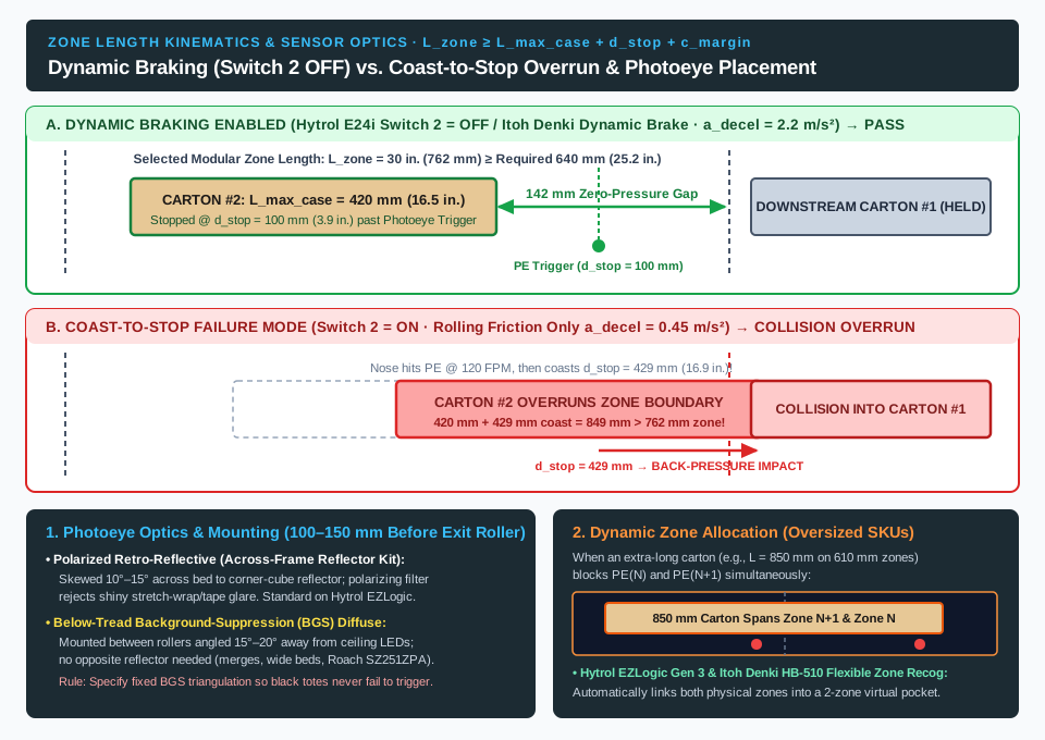
L_max_case: Maximum package length along the direction of travel (mm). If cartons can enter skewed by angleθ(5° to 10°after a curve or merge), use the swept diagonal envelopeL_skew = (L × cos θ) + (W × sin θ).v: Conveyor linear speed inm/s(FPM × 0.00508 = m/s; for example,120 FPM = 0.610 m/sand174 FPM = 0.884 m/s).t_scan: Photoeye debounce and driver card reaction latency (0.015 to 0.040 s, with0.025 sas the design baseline).a_decel: Effective package deceleration rate (m/s²). With dynamic braking enabled (Hytrol E24i Switch 2 = OFFper Bulletin #669, p. 6,Itoh Denki PM486FEbuilt-in dynamic brake, orInterroll MultiControlstop ramp) on dry corrugated board over steel rollers (μ ≈ 0.25–0.35), effective deceleration isa_decel ≈ 1.8 to 2.8 m/s². When set to coast-to-stop (Hytrol Switch 2 = ON), deceleration drops to rolling friction alone (a_decel ≈ 0.3 to 0.6 m/s²), multiplying stopping travel by4× to 6×.c_margin: Static inter-package air gap (100 to 200 mm/4 to 8 in.) ensuring the trailing tail of Carton #1 clears the upstream zone boundary and never contacts the nose of Carton #2.
Worked comparison: 420 mm shipping case at 120 FPM (0.610 m/s)
Evaluate a sealed corrugated case with L_max_case = 420 mm (16.5 in.) running at v = 120 FPM (0.610 m/s), t_scan = 0.025 s, and required clearance margin c_margin = 120 mm (4.7 in.):
- With dynamic braking enabled (
Hytrol E24i Switch 2 = OFF,a_decel = 2.2 m/s²):- Scan reaction travel:
0.610 m/s × 0.025 s = 0.0153 m (15.3 mm) - Braking deceleration travel:
0.610² ÷ (2 × 2.2) = 0.3721 ÷ 4.4 = 0.0846 m (84.6 mm) - Total stopping distance:
d_stop = 15.3 mm + 84.6 mm = 99.9 mm ≈ 100 mm (3.9 in.) - Minimum required zone length:
L_zone ≥ 420 mm + 100 mm + 120 mm = 640 mm (25.2 in.) - Modular frame selection: A
24 in. (610 mm)zone is30 mmtoo short (leaving only 90 mm static clearance), whereas selecting the next standard increment—a30 in. (762 mm)zone onHytrol 190-E24EZorRoach Smart MDR—provides a242 mmpost-trigger envelope (100 mmbraking stop +142 mm (5.6 in.)static zero-pressure air gap).
- Scan reaction travel:
- Failure mode—Coast-to-stop enabled (
Hytrol E24i Switch 2 = ON,a_decel = 0.45 m/s²):- Braking deceleration travel balloons to
0.610² ÷ (2 × 0.45) = 0.3721 ÷ 0.90 = 0.4134 m (413.4 mm) - Total stopping distance:
d_stop = 15.3 mm + 413.4 mm = 428.7 mm ≈ 429 mm (16.9 in.) - Total zone space consumed:
420 mm + 429 mm = 849 mm (33.4 in.), which exceeds a30 in. (762 mm)zone by87 mm, driving the nose of Carton #2 directly into the halted Carton #1 downstream.
- Braking deceleration travel balloons to
3. Handling oversized SKUs: Dynamic Zone Allocation and Flexible Zone Recognition
When a multi-SKU packaging line occasionally introduces an extra-long carton (for example, L_case = 850 mm on a conveyor framed with 24 in. / 610 mm physical zones), a single carton spans two zones and blocks both PE(N) and PE(N+1) simultaneously. On a basic fixed-zone card, the trailing zone either faults on a jam timer or drives into the rear of the long box. Specify Hytrol Gen 3 EZLogic Dynamic Zone Allocation or Itoh Denki HB-510 Flexible Zone Recognition, which automatically merge two adjacent physical zones into a temporary 2-zone (1,220 mm) virtual pocket whenever a single package blocks both photoeyes concurrently, and pair HB-510 Stable Speed closed-loop regulation so light (3 kg) and heavy (25 kg) cartons travel at identical FPM without closing their gaps.
4. Photoeye placement geometry and optical selection
Mount each zone’s photoeye 100 to 150 mm (4 to 6 in.) upstream of the zone’s last (discharge) roller so the 100 mm dynamic braking distance brings the carton nose to a full stop before overhanging the zone boundary.
| Sensor optical architecture | OEM configuration reference | Mounting geometry and optical principle | Application strengths and failure prevention |
|---|---|---|---|
| Polarized retro-reflective photoeye (across-frame reflector) | Standard on Hytrol EZLogic (Reflector Kit, Bulletin #669 p. 18) and Interroll MCP |
Side-channel emitter/receiver aims a polarized visible-red beam across the bed (skewed 10°–15° in plan view just above roller top tangent) onto an opposite corner-cube reflector |
Detects full bed width regardless of package color; polarizing filter rejects false reflections from glossy stretch film, clear sealing tape, or foil labels. Requires side channels on both sides |
Background-suppression (BGS) diffuse photoeye (below-tread) |
Hytrol EZLogic Diffuse option (EZLogic Brochure, p. 4) and Roach SZ251ZPA below-tread sensors |
Mounted between two tread rollers below the conveying plane, angled 15°–20° away from overhead high-bay LED fixtures to sense the carton bottom |
Eliminates across-frame reflectors on wide beds, merges, and pallet conveyors (Roach SZ251ZPA). Specify fixed background-suppression triangulation (BGS) so matte-black totes trigger reliably and ceiling lights cannot false-trip the sensor |
Key takeaway: Enforce P_roller ≤ L_min_case ÷ 3 (3.0 in. centers for cases ≥ 229 mm, 2.0 in. centers for 152–190 mm trays), keep Hytrol E24i Switch 2 = OFF (dynamic braking enabled), and mount polarized retro-reflective or BGS diffuse photoeyes 100–150 mm upstream of each zone’s exit roller so d_stop (~100 mm at 120 FPM) finishes inside the zone with ≥ 100–150 mm clearance.
Singulation vs slug release conveyor logic: throughput math and jam protection
How cartons accumulate and how they discharge from the buffer are governed by the release mode selected in Hytrol Bulletin #669 (pp. 5, 7), the Hytrol EZLogic Brochure (p. 10), Itoh Denki HB-510 / IB-E03A, and Interroll MultiControl AI/BI (Single vs. Train Release). Choosing between a singulation vs slug release conveyor mode alters effective line throughput by +36% to +94% at the exact same roller FPM.
1. Singulation Mode (Single / Sequential Release)
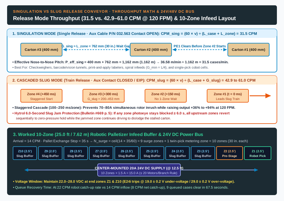
In Singulation Mode, when the downstream hold signal clears, Zone #1 drives Carton #1 across the discharge boundary while Zone #2 remains stopped until Carton #1 completely clears Zone #1’s photoeye (Controller A). Only when Zone #1’s sensor transitions from blocked (1) to clear (0) does Zone #2 energize its MDR to advance Carton #2. During loading, if upstream cartons arrive spaced closer than one zone length apart, the conveyor actively separates (singulates) them until an approximate one-zone-length gap (G_sing ≈ L_zone) exists between every package:
P_eff_sing ≈ L_case + L_zone
CPM_sing = (60 × v) ÷ (L_case + L_zone)
2. Slug Mode and Cascaded Slug Release (Train / Block Release)
In Slug Mode (Train Release), cartons arriving spaced less than one zone length apart do not separate while traveling down the conveyor, although each carton still halts in its own independent zone with zero line pressure when the queue backs up (Hytrol Bulletin #669, p. 5). When the discharge hold signal de-activates, occupied zones release as a contiguous train without waiting for each downstream photoeye to clear:
P_eff_slug = L_case + G_slug
CPM_slug = (60 × v) ÷ (L_case + G_slug)
Starting 15 or 20 MDR zones at the exact same millisecond creates two engineering hazards: a simultaneous locked-rotor acceleration current spike (20 motors × 3.5–4.0 A peak = 70–80 A) that trips the 24V DC power supply overcurrent circuit, and rear cartons bumping leading cartons if motor ramp rates vary slightly. Cascaded Slug Release (Hytrol E24EZ Product Focus Sheet and EZLogic Brochure, p. 10) introduces a momentary staggered delay (Δt_cascade ≈ 100 to 250 ms per zone, propagating upstream from Zone #1 to Zone #N). This spreads motor starting inrush across 2 to 4 seconds while maintaining a tight, uniform inter-carton spacing.
3. Worked throughput calculation at 120 FPM (36.58 m/min)
Compare a singulation vs slug release conveyor operating at v = 120 FPM = 0.6096 m/s (36.58 m/min) carrying L_case = 400 mm (0.400 m) cartons on standard L_zone = 30 in. (762 mm = 0.762 m) zones:
- Singulation Mode sustained discharge rate:
- Effective nose-to-nose pitch:
P_eff_sing = 0.400 m + 0.762 m = 1.162 m - Maximum throughput:
CPM_sing = 36.58 m/min ÷ 1.162 m = 31.5 cases/min
- Effective nose-to-nose pitch:
- Cascaded Slug Mode discharge rate (
Δt_cascade = 0.15 sper zone):- Releasing from a stopped accumulated queue: Each carton sits at its zone photoeye (
762 mmnose-to-nose static pitch) plus the dynamic cascade stagger (0.610 m/s × 0.15 s = 91.5 mm), givingP_eff_slug = 762 mm + 91.5 mm = 853.5 mm (0.8535 m). Discharge rate jumps toCPM_slug = 36.58 m/min ÷ 0.8535 m = 42.9 cases/min(+36.2%over singulation). - Continuous un-gapped slug transport (
G_slug = 200 mminter-case gap): Effective pitch tightens toP_eff_slug = 0.400 m + 0.200 m = 0.600 m, deliveringCPM_slug = 36.58 m/min ÷ 0.600 m = 61.0 cases/min(+93.7%over singulation) at the same120 FPMroller speed—without accelerating rollers to high speeds that tip tall cartons.
- Releasing from a stopped accumulated queue: Each carton sits at its zone photoeye (
4. Mandatory 6-second Slug Jam Protection and on-the-fly mode switching
Because Slug Mode suppresses zone-to-zone separation during continuous flow, a physical jam (such as a damaged flap snagging a guide rail) otherwise allows upstream zones to push into the stalled carton. Hytrol Bulletin #669 (p. 5, Jam Protection — Slug Mode Only) enforces a deterministic protection timer: if any zone photoeye remains continuously blocked for 6.0 seconds or longer while running in Slug Mode, all zones upstream of the blocked sensor revert sequentially to zero-pressure accumulation hold, while the single zone containing the jammed carton continues driving to dislodge the obstruction. As soon as the photoeye clears, upstream zones resume slug flow automatically.
| Operational criterion | Singulation Mode (Single Release) |
Slug / Cascaded Slug Mode (Train Release) |
|---|---|---|
| Primary downstream equipment | In-motion checkweighers, barcode/vision tunnels, print-and-apply labelers, spiral infeeds (Ryson G_min = L/4 rule), and single-pick cobots (FANUC CRX-30iA) |
Row-forming layer palletizers, multi-case robot grippers (picking 2–4 cases/cycle), high-speed merge windows, and rapid buffer recovery after pallet exchange |
Inter-package gap (G) |
Enforced G_sing ≈ L_zone (457–914 mm) during both travel and discharge |
G_slug = 150–453 mm (L_zone - L_case + v × Δt_cascade from queue; 100–250 mm continuous) |
Effective throughput at 120 FPM (400 mm case, 762 mm zone) |
31.5 cases/min (limited by wait-until-downstream-clear logic) |
42.9 cases/min (from stopped queue) to 61.0 cases/min (continuous) |
| Jam protection logic | Self-limiting; upstream zone halts immediately when downstream photoeye stays blocked | Requires 6.0 s Slug Jam Timer (Bulletin #669, p. 5) to revert upstream zones to zero-pressure hold |
| On-the-fly PLC switching method | Dry-contact OPEN on Hytrol Auxiliary Input Cable P/N 032.563 (Bulletin #669, p. 7) or fieldbus Single Release bit |
Dry-contact CLOSED on Hytrol P/N 032.563 (zero external voltage applied) or IB-E03A / MultiControl Train Release bit |
When wiring Hytrol Auxiliary Input Cable P/N 032.563 (Bulletin #669, p. 7) to toggle modes on the fly, connect the two auxiliary leads only to an isolated dry-contact relay output (OPEN = Singulation, CLOSED = Slug). Never apply external 24V DC voltage to the auxiliary leads, and never wire multiple zone controllers across a single relay contact. On networked conveyors using Itoh Denki IB-E03A (EtherNet/IP with DLR and Rockwell AOP) or Interroll MultiControl AI/BI (PROFINET, EtherNet/IP, EtherCAT), the PLC switches individual zones between Single and Train release over the cyclic network image while keeping photoeye-to-MDR braking local (< 5 ms card interrupt) so network scan jitter never delays a stop.
Key takeaway: Use Singulation Mode (31.5 CPM at 120 FPM) where downstream scanners, checkweighers, or spiral conveyor infeeds require a guaranteed gap, and switch to Cascaded Slug Mode (42.9–61.0 CPM) with 6.0 s jam protection active when feeding multi-case robot grippers or draining an accumulated queue after a pallet exchange.
24V/48V DC power bus rules, sleep-timer duty cycles, and a worked 10-zone palletizer infeed
1. 24V and 48V DC power supply sizing and branch topology
Under-sizing or end-feeding a 24V DC bus is the primary electrical cause of intermittent zone dropouts during slug release:
- Hytrol
≤ 20 motorsper20Abranch rule (Bulletin #669, pp. 6, 8–12): EachE24ibrushless motor card draws1.5 Anominal continuous current (protected by a5.0 Ainternal fuse and electronic current limiting indicated by the Amber LED) and requires a terminal supply voltage within22.0 to 28.0 VDC—tripping on under-voltage at19.0 ± 0.2 VDC(2 or 3 red LED flashes) and over-voltage at29.0 ± 0.2 VDC. Never connect more than20 drive cards and motorsto a single20 A24V DC output branch (19 motors max per side on 115VAC plug-in MC models). For21 to 40 zones, mount a40 A24V DC power supply at the physical center of the conveyor, feeding≤ 20 zonesupstream from one20 Aoutput side and≤ 20 zonesdownstream from the second20 Aoutput side. - Interroll
MultiControlisolated logic vs. motor buses and brake chopper (MultiControl AI/BI Datasheet, pp. 44–46):MultiControlseparates the 24V DC logic and sensor bus (max 0.2 Acard +1.6 Asensors) from the RollerDrive motor power bus (24V DC: 22–28 Vor48V DC: 44–56 V) and includes an onboard brake chopper to clamp regenerative back-EMF (< 29 Vor< 56 V) when heavy totes decelerate rapidly. When a robot cell guard door opens or an E-stop trips, the safety relay drops only the motor power bus—bringing allEC5000rollers to a safe torque-off halt while keeping the 24V logic supply, fieldbus, and all photoeyes live. That preserves exact zone-occupancy tracking across the “Transfer interrupted” state defined in our palletizing conveyor handoff table.
2. Run-On-Demand sleep timer duty cycle and energy balance
Unlike a continuous AC line-shaft or flat-belt accumulator driven by a 1.5 to 2.2 kW (2 to 3 HP) 480V 3-phase motor running 100% of every shift, a 24V MDR zone equipped with a Run-On-Demand Sleep Timer (Hytrol EZLogic Sleep Feature, Itoh Denki PM486FE, or Interroll MultiControl) energizes its roller only while a carton transits that zone:
D_zone = (N_cases_per_min × t_pass_sec) ÷ 60
For a 400 mm carton crossing a 762 mm zone at 120 FPM (0.610 m/s), transit time is t_pass = (0.762 + 0.400) ÷ 0.610 = 1.90 s (or ~2.5 s including wake/sleep ramp). At an average arrival rate of 15 cases/min, active motor duty cycle is D_zone = (15 × 2.5 s) ÷ 60 = 62.5% during flow and 0% (< 2 W card quiescent draw) whenever the zone is empty or holding a stationary accumulated carton, reducing conveyor electrical consumption by 50% to 75%, lowering plant noise by 10 to 15 dBA, and eliminating roller-slip scuffing on bottom carton flaps.
3. Worked 10-zone (25.0 ft) robotic palletizer infeed sizing calculation
Consider a packaging line where sealed cases exit a case packer downstream of a RoboSELEX primary collating module at a steady arrival rate of 14 cases/min and feed a robotic palletizer cell. Every finished pallet requires a 35-second full-pallet discharge and empty-pallet reload interruption (combining the 10 to 15 s empty-pallet release from our pallet dispenser machine guide with full-pallet transfer to downstream containment covered in our stretch-wrap vs. banding review and our rotary arm stretch wrapper vs. turntable integration guide).
- Step 1 — Package envelope and roller pitch check:
- Carton dimensions:
L = 400 mm (15.75 in.) × W = 300 mm (11.8 in.), massm = 16 kg (35.3 lbs)(matched to the layer geometry in our palletization calculator guide). - Minimum roller pitch:
P_max = 400 mm ÷ 3 = 133.3 mm (5.25 in.). Selecting standard3.0 in. (76.2 mm)centers places400 ÷ 76.2 = 5.25(5 to 6 rollers) under every carton.
- Carton dimensions:
- Step 2 — Zone length and dynamic braking check at
120 FPM (0.610 m/s):- With
Hytrol E24i Switch 2 = OFF(d_stop = 100 mm) andc_margin = 120 mm: L_zone ≥ 400 mm + 100 mm + 120 mm = 620 mm (24.4 in.).- Select standard
30 in. (762 mm / 2.5 ft)modular zones with Poly-V (PJ) belt slave transmission (16 kg / 35.3 lbsper carton is within the75 lbs/zone190-E24EZand120 lbs/zoneE24EZstructural ratings while benefiting from positivePoly-Vbraking repeatability).
- With
- Step 3 — Surge zone count and total conveyor length:
- Applying the macro stop equation (
Additional waiting units = incoming units/min × stop duration in min) from Palletizing Conveyors: Accumulation and Handoff Interfaces: N_surge = ceil[14 cases/min × (35 s ÷ 60 s/min)] = ceil(8.17) = 9 surge accumulation zones.- Adding
1dedicated robot pick/metering discharge zone (Zone #1) yields10 zones total (Zones #1–#10). - Total ZPA conveyor length:
10 zones × 2.5 ft/zone = 25.0 ft (7.62 m)(constructed from two10-ftframe sections of four30-in.zones each plus one5-ftsection of two30-in.zones).
- Applying the macro stop equation (
- Step 4 — Hybrid release recovery and queue pump-down time:
- When the new empty pallet locks onto the cell datum after
35 s,9 cartonsoccupyZones #2–#10while new cartons continue arriving at14 CPM. The robot uses a dual-case tool (2 cases/pick) capable of22 cases/min(net catch-up rate = 22 − 14 = 8 cases/min). - Configure
Zones #3–#10in Cascaded Slug Mode (42.9 CPMdischarge rate) so the queued train advances without762 mmsingulation delays, whileZone #2andZone #1execute a two-case metered release interlocked with the robot’sReady to Pickhandshake. - Queue recovery duration:
9 queued cases ÷ (22 − 14 cases/min) = 1.125 minutes (67.5 seconds)to return the buffer to zero occupancy without pausing the upstream case sealer.
- When the new empty pallet locks onto the cell datum after
- Step 5 — 24V DC power supply verification:
10 zones × 1.5 A nominal/zone = 15.0 A(≤ 20 motors/branch limit), powered by a single20 A24V DC power supply mounted at the12.5-ftcenter point of the25.0-ftframe.
4. Factory acceptance testing (FAT) and commissioning verification table
Integrate this verification record with your overall robotic palletizing cell acceptance checklist and packaging line integration plan before signing off on conveyor commissioning:
| Commissioning test item | Target acceptance criterion | Dominant failure mode prevented |
|---|---|---|
| 1. Minimum 3-roller pitch and bed squareness | P_roller ≤ L_min_case ÷ 3 (≥ 3 rollers under shortest SKU); frame diagonal measurements A and B equal within ≤ 1.5 mm (1/16 in.) (Bulletin #669, Fig. 5B) |
Carton tipping into roller valleys, photoeye beam bounce, and side-rail skew tracking |
2. Dynamic braking stopping travel (d_stop) |
Switch 2 = OFF / dynamic brake active; heaviest SKU halts within 100–150 mm of photoeye trigger at full operating FPM, leaving ≥ 100 mm air gap before next zone |
Coast-to-stop overrun (429 mm at 120 FPM) causing back-pressure collisions across zone boundaries |
| 3. Oversized / skewed carton zone allocation | Longest SKU (or carton skewed 10°) blocking two adjacent photoeyes concurrently allocates a 2-zone virtual pocket (Dynamic Zone Allocation / Flexible Zone Recognition) |
Trailing zone driving into the tail of a long carton or nuisance jam fault lockouts |
| 4. Singulation vs. Cascaded Slug and 6.0 s Jam Timer | Verify dry-contact (P/N 032.563) or fieldbus mode switch; hold a carton over an active Slug photoeye for ≥ 6.0 s and confirm all upstream zones halt sequentially in zero-pressure hold (Bulletin #669, p. 5) |
Multi-case pile-up and carton crushing during a guide-rail jam in Slug Mode; 24V DC bus inrush trip on simultaneous start |
| 5. End-zone DC bus voltage under cascade start | ≤ 20 motors per 20 A supply branch; measure terminal voltage at farthest end-zone card during a full-queue cascade start—must stay within 22.0 to 28.0 VDC (well above 19.0 VDC trip) |
End-of-line motor card brownout (2/3 red LED fault flashes) and sluggish release during peak buffer recovery |
Key takeaway: Limit every 20 A 24V DC supply branch to ≤ 20 MDR zones with center-fed cabling (maintaining 22.0–28.0 VDC under cascade start), specify isolated motor versus 24V logic power buses (Interroll MultiControl) so E-stops never erase zone occupancy memory, and verify the 6.0 s slug jam timer and d_stop ≤ 100–150 mm braking distance with the heaviest production carton during factory acceptance testing.
Technical basis and scope
This reference draws on published equipment manuals and product data sheets from Hytrol Conveyor Company (E24EZ 24VDC Roller Accumulating Conveyor Product Focus Sheet, updated November 2025; E24 24-Volt Conveying System Brochure, Bulletin #713; Model 190-E24EZ, 190-E24, 190-E24MC Installation and Maintenance Manual, Bulletin #669; and EZLogic Zero-Pressure Accumulation System Brochure), Itoh Denki USA (PM486FE Motorized Conveyor Roller and HB-510, IB-E03A, and CB-016S7 Driver Cards technical specifications), Interroll Group (MultiControl AI/BI Four-Zone ZPA Controller and RollerDrive EC5000 24V/48V Product Data Sheet), and Roach Conveyors / Pro Pac (Smart MDR Straight Accumulation Conveyor and SZ251ZPA Smart Zone Heavy-Duty Zero Pressure Accumulator specifications). Verify final roller gauge, transmission belt profile, zone length, deceleration ramp, and power supply branch sizing against the supplied equipment manual and approved general arrangement drawing. Reviewed October 2026.