On this page
A blocked discharge can cause downtime along an otherwise compact elevation route. Plan a spiral conveyor system by fixing the elevation, reserving the full installed footprint and defining the infeed and outfeed behavior before selecting its conveying capacity.
A spiral conveyor system carries products around a rising or descending path between levels. Compare it with an incline or lift using the entire installation: transfer tangents, product envelope, access and waiting space belong on the layout alongside the spiral frame. Then check whether the actual product can enter, travel and leave in its required orientation. Compact vertical transport does not automatically provide a buffer for a stopped downstream process.
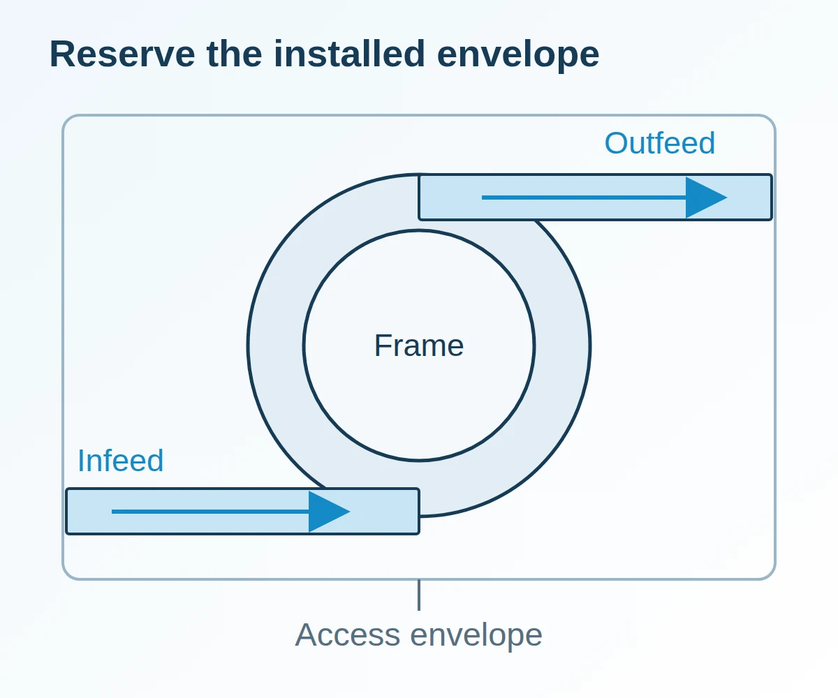
Fix the elevation and envelope on one drawing
Use the actual conveyor transfer elevations as the vertical datums. A mezzanine floor level alone does not define the top conveying surface or the available headroom.
| Input or item | Typical value or source | Why it matters |
|---|---|---|
| Infeed and outfeed surface elevations | Survey and approved general arrangement | Defines the required rise or descent |
| Product envelope and orientation | Actual packed product and trial record | Includes bulging and the largest swept envelope |
| Frame and tangent envelope | Selected manufacturer’s drawing | Defines occupied floor area beyond the circular section |
| Access and removal space | Site maintenance and access plan | Allows inspection and component replacement |
| Inclination, speed and simultaneous load limits | Manual and drawing for the supplied unit | Avoids treating a product-family description as an application rating |
Ryson’s product overview describes a compact continuous vertical path with horizontal entry and exit sections. It distinguishes case conveying, mass flow and vertical accumulation products. Select the equipment category before transferring assumptions between them.
Show the product above the conveying surface at every overhead obstruction. Mark the structural support interface and the maintenance access route, and verify all envelope dimensions against the approved general arrangement drawing.
Compare the installation’s likely failure point
Choose the vertical route that fits both flow and recovery requirements. A small frame has limited value if the transfer queue obstructs the adjoining line.
| Route | Question to resolve | Dominant failure mode and prevention |
|---|---|---|
| Continuous spiral | Can products transfer reliably at both elevations? | Discharge backup or entry misalignment; define receiving availability and controlled release |
| Straight incline | Is there enough horizontal run for the chosen rise and product behavior? | Product sliding or tipping; verify belt, inclination and starts with the actual package |
| Intermittent vertical lift | Can the transfer cycle accommodate the arrival pattern? | Waiting queue grows between cycles; size the queue and define upstream holding |
| Dedicated accumulation system | Is waiting capacity explicitly part of the equipment duty? | Storage is assumed from visible conveyor length; specify usable positions and release behavior |
For a spiral proposal, request a marked drawing showing entry direction, exit direction and rotation. Two arrangements with the same rise can connect very differently to the existing conveyors.
Check the infeed as a physical transfer
The package must arrive aligned and supported before it begins the curved path. Check the smallest base and the least rigid product at the boundary, including its orientation after upstream turning.
Ryson’s integration guide, section 5, requires powered transfers and positioning within the slat width before entry. It specifies an infeed surface 1/8–1/4 inch above the spiral and an outfeed surface 1/8–1/4 inch below it.
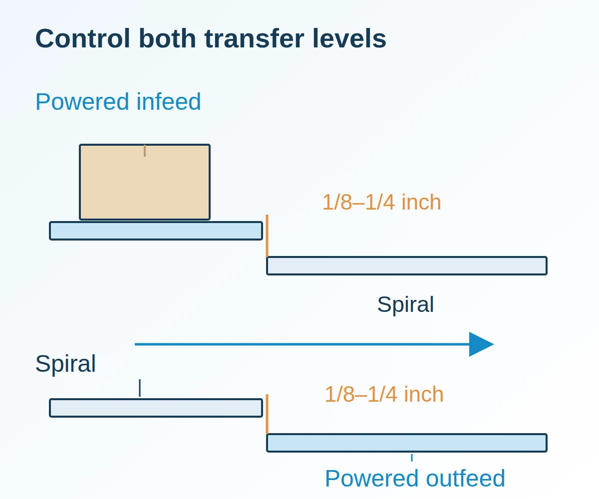
Record the actual support discontinuity as well as the level difference. Inspect for a soft leading edge catching, a small package losing support, or a turned case contacting a guide. A successful transfer of the largest rigid carton does not settle the behavior of the smallest flexible pack.
Set the spacing threshold before the spiral
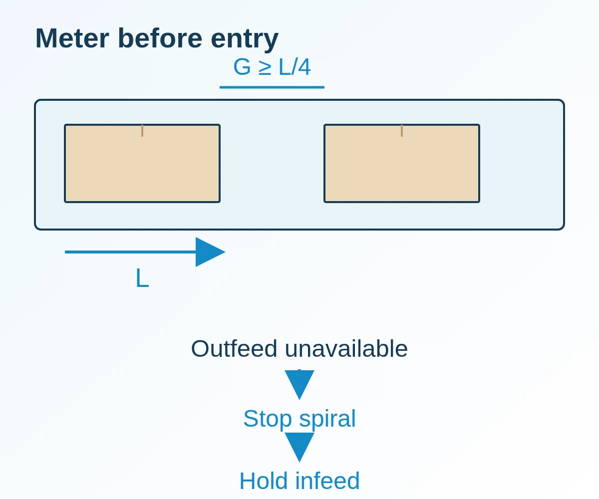
Use upstream metering to establish the required separation. Ryson’s guide, section 4, sets a minimum entry gap of a quarter of product length and notes that heavier loading can require more. The spiral itself is not the device that creates this separation.
Physical threshold rule: for the Ryson arrangement described in that guide, if entry gap G is less than L/4, hold the next product upstream and restore spacing before release. Meeting that minimum still requires the unit’s loading and product checks.
G_min = L/4, where L is product length in the direction of travel.
Worked line: for a measured carton length L = 400 mm, G_min = 400 mm ÷ 4 = 100 mm.
Use the worst permitted product sequence when different lengths share the same infeed; a setting checked with one carton may not suit the next recipe.
Prove blocked-outfeed recovery
The acceptance exercise should include an unavailable receiver, products near both transfers and a subsequent controlled restart. Define which controller owns each release and how the physical product state is confirmed.
Ryson’s guide requires matched conveyor speeds, the spiral at full operating speed before infeed starts, and a spiral stop when outfeed is full or stopped. Translate those requirements into observable acceptance conditions for the installed controls. Record whether a package remains supported during stopping and whether the next release preserves separation. Process handshakes do not replace the installation’s safety design.
Keep a recovery record for an ordinary downstream stop, a jam and a manual product removal. The conveying systems collection provides the broader transport-versus-buffer distinction; use the palletizing conveyor handoff guide to define waiting capacity outside the elevation section, and size the upstream 24V MDR metering zones and singulation release gaps with the zero pressure accumulation conveyor photoeye zones guide.
Include access and interrupted flow in total cost
Compare total cost over the same operating period, including energy measured under comparable product flow, wear parts, inspection, recovery labor and the production time lost during blocked transfers. Keep the proposed maintenance access on the layout: a compact frame can still require substantial removal space.
Keep a ledger over one recorded operating period and product range:
| Ledger entry | Record and unit | Period calculation |
|---|---|---|
| Energy use | Meter readings, kWh | Closing reading minus opening reading for the same equipment boundary |
| Wear parts and rejected product | Parts replaced and products rejected, counts by type | Total each part or product type separately |
| Inspection labor | Inspectors and minutes per inspection | Sum inspectors × minutes, in person-minutes |
| Recovery labor | Recovery events, workers per event and minutes each | Sum events × workers × minutes, in person-minutes |
| Line downtime | Stop and restart timestamps, minutes | Sum non-overlapping blocked-transfer and maintenance stops |
| Accepted output | Products conveyed, count | Record accepted output alongside the period totals to compare equivalent duties |
Worked period example: 4 recovery events × 1 worker per event × 6 minutes each = 24 person-minutes of recovery labor. When the same operating period records 18 minutes of line downtime, retain 18 line-downtime minutes as a separate entry. Inspection excludes recovery work already logged, and overlapping stop intervals count once.
Link the evaluation to the packaging line integration collection so that upstream holding and downstream recovery are counted with the elevation equipment.
Technical basis and scope
This reference draws on Ryson International’s Spiral Integration and Maintenance Guide and vertical conveying product specifications. Verify final model selection, incline angle, speed, and simultaneous load limits against the supplied equipment manual and general arrangement drawing.