On this page
Size the waiting capacity and define the release handshake before choosing a palletizing conveyor layout. Separate the cases arriving at the robot from the finished pallets leaving it: they are different loads with different transfer requirements.
Decide what the conveyor must carry
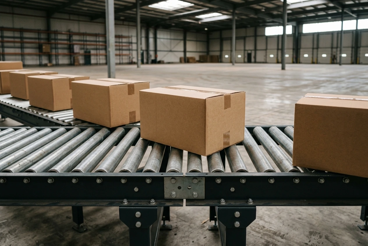
A case infeed presents individual packages to a pickup position. A loaded-pallet conveyor carries the complete unit load and its pallet. Do not reuse a case-conveyor rating, transfer assumption or stopping method for the pallet side without checking the selected equipment.
Write down the smallest supported footprint, the largest load envelope and the relevant mass for each section. A layout should show the actual base or pallet runners that contact the conveying surface. Check the product at transfers, where support changes, rather than inspecting only the middle of a straight conveyor.
Give accumulation its own requirement
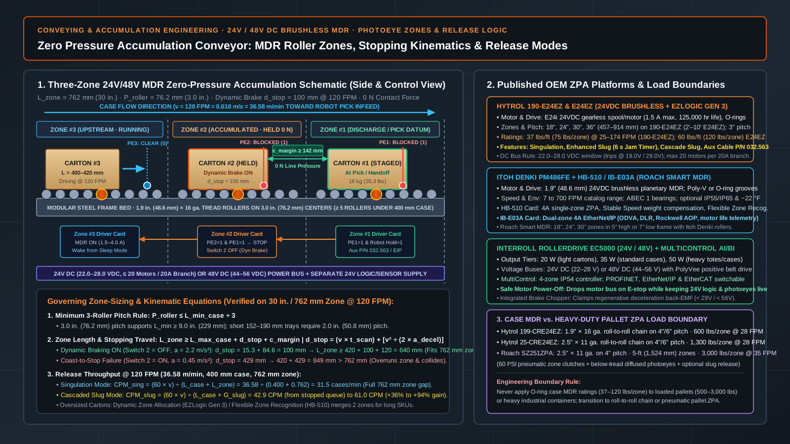
Hytrol describes zero-pressure accumulation as zone-based holding and movement with separation between products. That explains one way to avoid product-to-product contact; it does not establish the capacity or suitability of every conveyor. Hytrol’s explanation should be read alongside the manual for the selected unit.
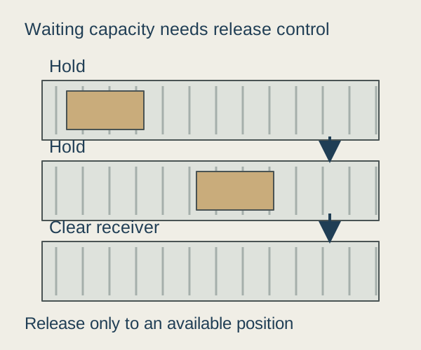
Decide whether cases may touch, whether they must retain order and how they leave the buffer. A line may need one-at-a-time release into a robot pick position even when several cases can be held upstream. Physical storage capacity and controlled release capacity are separate questions. For 24V/48V motor-driven roller hardware, photoeye zone length equations, dynamic braking, and singulation versus cascaded slug release math, see our zero pressure accumulation conveyor and photoeye zone sizing guide.
Calculate a stop requirement in units first
For a complete downstream stop with steady incoming flow, a first estimate is:
Additional waiting units = incoming units per minute × stop duration in minutes.
For example, an infeed arrival rate of 12 cases per minute during a 30-second pallet exchange requires 6 zones of surge accumulation capacity while pallet release is paused, plus allowance for existing queue occupancy and zone pitch spacing.
After restart, the downstream process must have spare capacity to clear the queue while arrivals continue. If it can only match arrivals, the queue remains. Measure the real stop distribution and recovery behavior before deciding which interruption the buffer is meant to absorb. A buffer sized for a short pallet exchange may be unable to cover a maintenance stop.
Agree the handoff with both machine owners
A control diagram should identify who requests a transfer, who grants it and who confirms completion. The exact signal names belong to the integrator. The interface table below defines the state transitions and handshake conditions between upstream and downstream controllers.
| Event | Agreement needed | Acceptance evidence |
|---|---|---|
| Receiver unavailable | Sender holds the next load in a supported position | No load released into an occupied or unavailable destination |
| Receiver ready | One owner authorizes motion across the boundary | A single intended transfer without duplicate release |
| Transfer interrupted | Both sides retain a known load state | Recovery identifies the load and destination before motion |
| Buffer full | Upstream release stops or an agreed alternative handles product | No unassigned buildup at the preceding machine |
| Product absent unexpectedly | Fault behavior distinguishes a gap from a lost load | Controlled recovery without a false completed transfer |
Do not treat these process signals as a complete safety design. The responsible designers must handle stopping functions, access and restart conditions for the installation.
Verify recovery with real product states
Include partly occupied zones, a full buffer and a product straddling a transfer in the agreed review. The physical state after a stop matters more than whether each drive can run on its own. Retain a record of what the operator is allowed to remove or reposition before restart.
If the next station restrains the load, coordinate its receiving datum and waiting space with the stretch-wrap and banding review and size upstream full-pallet surge zones for film roll changes, turntable 0° roller homing, and muting light curtains with the rotary arm stretch wrapper vs turntable integration guide. An empty pallet released from a magazine is a separate load from the cases on this conveyor; size that stack and release with the pallet dispenser machine guide. Return to the conveying systems collection for the role of accumulation in the line.
Technical basis and scope
This conveyor handoff and buffer-sizing framework draws on Hytrol’s zero-pressure accumulation documentation and zone-release control principles to separate case-infeed singulation from heavy-duty unit-load pallet transport. Reviewed October 2026.